blackbetty97
LVC Member
I, as most of the mark VIII family have experienced the dreaded clock spring failure. Upon searching, I have found NO new clock springs for the gen 11. Also as equally as unfortunate, there are NO used ones within Ford at all, and a search on ebay/craigslist was fruitless. I thought I fixed the problem with a clock spring ribbon out of a continental, and made it fit, but in two weeks, my crunching and popping returned, and horn, cruise, and airbags were lost yet again.
Out of shear desperation to have my horn work to pass PA state inspection, I began my long and drawn out search. What I found, to my elation, was the clock spring for a 00-02 Lincoln LS, and 02 Thunderbird are EXACTLY the same mount, same black box, same ribbon, pretty much same everything, minus one small problem. The Airbag Connector is different, but the wires were the same color code, and same location.
I went to Ford, and purchased the 2000 Lincoln LS clock spring.
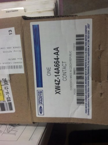
Got home and tore into the mark VIII. I know there are A LOT of threads with this information, but since I will be altering the new clock spring, I will include a Step by Step procedure of what I did. I make NNOO guarantees this will work for you, or that you should cut or splice wires, but this is what I did and it worked for me.
Step one, disconnect the battery.(I did not do this step, and did not have the air bag deploy, but this is on you if you don't/and it does)
Step two, remove kick plate. This pulls down with a little force. Be careful not to pull hard enough to break the light. Turn bulb and remove light from black kick plate.
Step Three, remove two 8mm bolts from the cover that hides your steering column under your dash. Once these are removed, pull the top gently. There are two pressure fittings on the right and left top that will pop out.
Step four, (this is why I did not connect my battery) raise your column up and forward all the way. There are two phillips screws under your column cover that need removed. Make sure they are completely out before trying to remove your lower cover. Gently pull your lower cover down. It will come off.
Step five, now lower your column completely, and out from the dash as far as it will go. Gently pull up on the top cover. There are two long plastic cylinders that slide through a notch, that the bottom screws screw into. DO NOT BREAK THEM. once the top and bottom cover are removed, set them aside.
Step six, remove the round plastic covers on the back of the steering wheel, and with a 8mm socket, remove the two bolts that hold on your air bag.
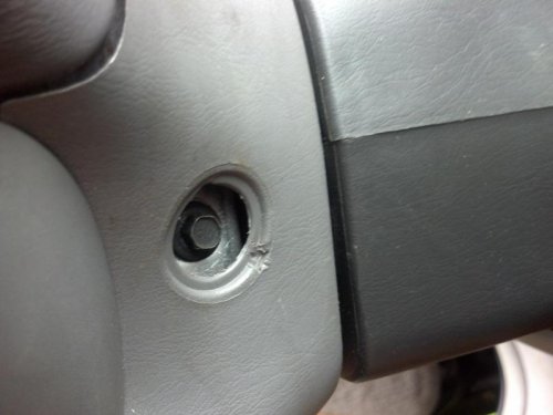
Step Seven, gently pull the air bag towards you. There is one connection behind it, for me it was Gray, but I have seen a black one there before as well. Push the tab on the connector, and gently pull the two apart. This separates your airbag from the steering wheel. Set it aside gently, and out of the way, so you don't accidentally set it off.
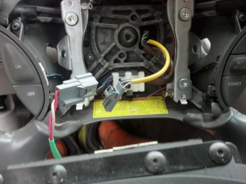
Step Eight, Remove the T50 retaining bolt, and disconnect the white connector at the bottom of the steering wheel.
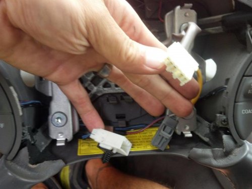
Step Nine, Remove your steering wheel. A wheel puller would help at this point, but feet on the dash, and a hard yank did the job for me. I also heard that the bolt wheel pullers just strip your steering holes out, so if I had to again, I would just get the two arm wheel puller, and grab the solid metal plate and pull it off that way. My pic shows the clock spring cable hanging out, but that is because I had it apart so many times, it popped off when I removed my steering wheel. Yours should still be inside, and you should only see the round black housing for it.
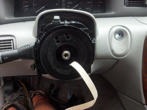
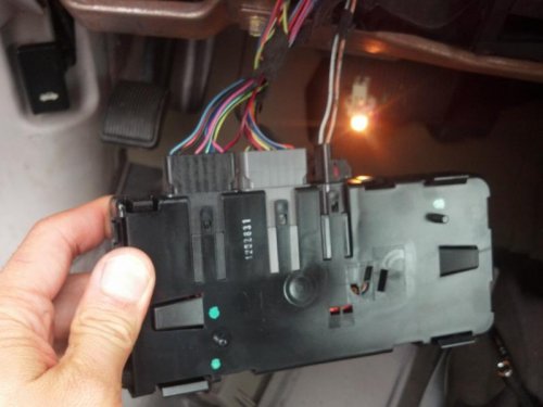
Step Ten, at this point, there are a few wire connections to unhook. Under the dash, you will see a black box attached to your steering column. Gently pull it down, and remove the 3 wiring harnesses that are connected to it. You will also see a white connector on the right side of the MFS(multi function switch) as well as a thin black one on right in front of the white one. The white connector pulls down, and the black connector pulls out in the direction of the dash. I did not get any pictures of the connecters that attach to the MFS, but you can clearly see them on the right side of the switch.
Step Eleven, once all of your connectors are disconnected from the MFS, and the 3 from the black box, you are ready to remove that dang blasted broken clock spring. there are 3 plastic clips that hold it to the MFS. Two on the top, and one on the side. I used my fingernail, and gently pulled at them, while wiggling the clock spring front. you will need to alternate which ones you pull, and such, as when you wiggle it, another one will pop back on. Also note, that the center round part is kind of tight on the steering shaft, so moving the clock spring mount, and the center plastic piece together will help. Its a little difficult, but not too bad.
Step Twelve, Take the Old clock spring, and the New clock spring into your shop, or kitchen table, or wherever you wanna do the surgery to it. You will need a wire cutter/stripper, flux, solder, steel wool, shrink tubbing and a soldering iron. On the OLD clock spring, cut the grey(or black) two wire connector off about mid way down the wires. Leave enough to work with. On the NEW clock spring, cut off the two wire black connector. The old connector is in the background of this picture. Save it, you will need it.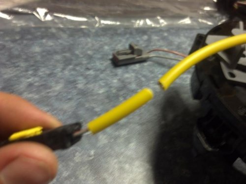
Step Thirteen, Strip both the connector wire, and the NEW clock spring wires, and gently twist the copper wire. I stripped about 1/4 inch off. Tin your wires, by applying flux to your iron, then applying a little solder. APPLY FLUX to your exposed copper wires, and gently touch the wires with the tip of the iron. No flux = no solder flow, and burnt wires.
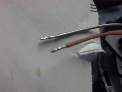
Step Fourteen, Once both of the wires are tinned, on both the OLD connector, and the NEW clock spring assembly, put shrink tubbing on each individual set of wires, then one over BOTH wires together. So you have 3 pieces, 2 small, and one thicker. Since you tinned the wires, soldering them together will be easy. MAKE SURE YOUR HOLDING THE CORRECT WIRES TOGETHER. Grey with white, and Grey with orange, DON'T cross solder them.. keep the colors the same!! Touch the corresponding wires together, overlapped a little, then touch the soldering iron to both wires at the same time. Solder will flow, and your connection will be made. Pull gently to make sure the connection is secure. Repeat for the second wire.
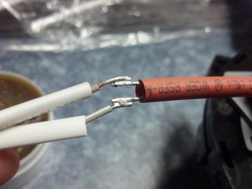
Step Fifteen, once your soldered connections are secure, move the two smaller shrink tube over them. Heat them up and watch them shrink! once the two thinner ones are done, move your thicker one over both connections. This ensures a solid connection, and doubles the insulation and abrasion resistance.
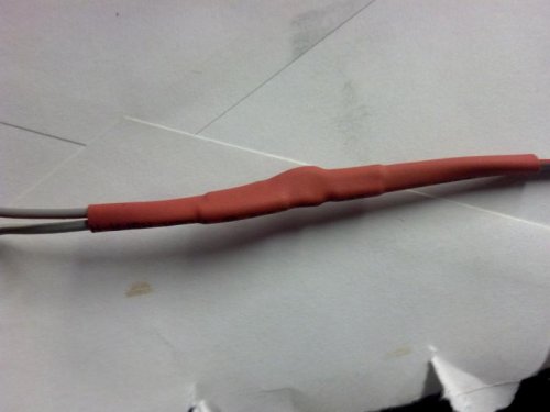
Congratulations.. you are half way there. your New clock spring is ready to be installed. Mine was set correctly from the factory with a grey plastic triangle holding it in place. DO NOT TAKE this off before installation. It will mess up your winding. Just install it as is, onto the MFS. Once it is installed, and clicked onto the MFS, then AND ONLY THEN, remove the gray plastic triangle.
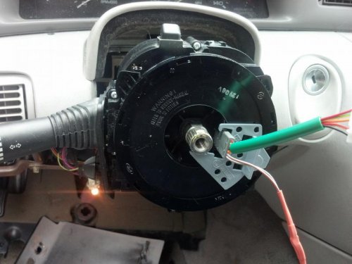
Step Seventeen, Reconnect your Black box connections, and your white and black connections to your MFS. You will notice there is an additional black connector on the new clock spring. This was an optional feature on the LS for steering wheel mic. Your mark VIII doesn't have it, so don't worry about connecting anything to it.
Reinstall your steering wheel, connect your white connector there, and replace your steering wheel retaining bolt.
Connect your air bag, and reinstall with your two 8mm bolts, and round plastic caps.
Move your column down, and reinstall the top cover, taking care not to break those long round plastic pieces, they kinda bend back into the holes a little, then wiggle it down and back till it pops back into place.
Move your Column back up, and reinstall the lower cover, and the two phillip screws
at this time, if you havent already, replace the "weather stripping" around your lower crotch cooler vent, then reinstall your lower panel, with the 8mm bolts.
Reinstall the light into your black plastic kick plate, and reinstall, making sure the prong goes into the hole at the back of the foot well, then push the connectors back up into the dash.
reconnect your battery (if you un hooked it)
start your car, press the horn, watch your airbag warning code 3,2 dissappear, and take a drive and marvel at your cruise control!!
I hope this helps someone else out there, as I was at my whits end with used ones breaking, and not being able to find them anyway.
LAST STEP...
Take that frackin old broke clock spring outside and shoot the livin day lights outta it!!!


Out of shear desperation to have my horn work to pass PA state inspection, I began my long and drawn out search. What I found, to my elation, was the clock spring for a 00-02 Lincoln LS, and 02 Thunderbird are EXACTLY the same mount, same black box, same ribbon, pretty much same everything, minus one small problem. The Airbag Connector is different, but the wires were the same color code, and same location.
I went to Ford, and purchased the 2000 Lincoln LS clock spring.

Got home and tore into the mark VIII. I know there are A LOT of threads with this information, but since I will be altering the new clock spring, I will include a Step by Step procedure of what I did. I make NNOO guarantees this will work for you, or that you should cut or splice wires, but this is what I did and it worked for me.
Step one, disconnect the battery.(I did not do this step, and did not have the air bag deploy, but this is on you if you don't/and it does)
Step two, remove kick plate. This pulls down with a little force. Be careful not to pull hard enough to break the light. Turn bulb and remove light from black kick plate.
Step Three, remove two 8mm bolts from the cover that hides your steering column under your dash. Once these are removed, pull the top gently. There are two pressure fittings on the right and left top that will pop out.
Step four, (this is why I did not connect my battery) raise your column up and forward all the way. There are two phillips screws under your column cover that need removed. Make sure they are completely out before trying to remove your lower cover. Gently pull your lower cover down. It will come off.

Step five, now lower your column completely, and out from the dash as far as it will go. Gently pull up on the top cover. There are two long plastic cylinders that slide through a notch, that the bottom screws screw into. DO NOT BREAK THEM. once the top and bottom cover are removed, set them aside.
Step six, remove the round plastic covers on the back of the steering wheel, and with a 8mm socket, remove the two bolts that hold on your air bag.

Step Seven, gently pull the air bag towards you. There is one connection behind it, for me it was Gray, but I have seen a black one there before as well. Push the tab on the connector, and gently pull the two apart. This separates your airbag from the steering wheel. Set it aside gently, and out of the way, so you don't accidentally set it off.

Step Eight, Remove the T50 retaining bolt, and disconnect the white connector at the bottom of the steering wheel.

Step Nine, Remove your steering wheel. A wheel puller would help at this point, but feet on the dash, and a hard yank did the job for me. I also heard that the bolt wheel pullers just strip your steering holes out, so if I had to again, I would just get the two arm wheel puller, and grab the solid metal plate and pull it off that way. My pic shows the clock spring cable hanging out, but that is because I had it apart so many times, it popped off when I removed my steering wheel. Yours should still be inside, and you should only see the round black housing for it.

Step Ten, at this point, there are a few wire connections to unhook. Under the dash, you will see a black box attached to your steering column. Gently pull it down, and remove the 3 wiring harnesses that are connected to it. You will also see a white connector on the right side of the MFS(multi function switch) as well as a thin black one on right in front of the white one. The white connector pulls down, and the black connector pulls out in the direction of the dash. I did not get any pictures of the connecters that attach to the MFS, but you can clearly see them on the right side of the switch.
Step Eleven, once all of your connectors are disconnected from the MFS, and the 3 from the black box, you are ready to remove that dang blasted broken clock spring. there are 3 plastic clips that hold it to the MFS. Two on the top, and one on the side. I used my fingernail, and gently pulled at them, while wiggling the clock spring front. you will need to alternate which ones you pull, and such, as when you wiggle it, another one will pop back on. Also note, that the center round part is kind of tight on the steering shaft, so moving the clock spring mount, and the center plastic piece together will help. Its a little difficult, but not too bad.
Step Twelve, Take the Old clock spring, and the New clock spring into your shop, or kitchen table, or wherever you wanna do the surgery to it. You will need a wire cutter/stripper, flux, solder, steel wool, shrink tubbing and a soldering iron. On the OLD clock spring, cut the grey(or black) two wire connector off about mid way down the wires. Leave enough to work with. On the NEW clock spring, cut off the two wire black connector. The old connector is in the background of this picture. Save it, you will need it.

Step Thirteen, Strip both the connector wire, and the NEW clock spring wires, and gently twist the copper wire. I stripped about 1/4 inch off. Tin your wires, by applying flux to your iron, then applying a little solder. APPLY FLUX to your exposed copper wires, and gently touch the wires with the tip of the iron. No flux = no solder flow, and burnt wires.

Step Fourteen, Once both of the wires are tinned, on both the OLD connector, and the NEW clock spring assembly, put shrink tubbing on each individual set of wires, then one over BOTH wires together. So you have 3 pieces, 2 small, and one thicker. Since you tinned the wires, soldering them together will be easy. MAKE SURE YOUR HOLDING THE CORRECT WIRES TOGETHER. Grey with white, and Grey with orange, DON'T cross solder them.. keep the colors the same!! Touch the corresponding wires together, overlapped a little, then touch the soldering iron to both wires at the same time. Solder will flow, and your connection will be made. Pull gently to make sure the connection is secure. Repeat for the second wire.

Step Fifteen, once your soldered connections are secure, move the two smaller shrink tube over them. Heat them up and watch them shrink! once the two thinner ones are done, move your thicker one over both connections. This ensures a solid connection, and doubles the insulation and abrasion resistance.

Congratulations.. you are half way there. your New clock spring is ready to be installed. Mine was set correctly from the factory with a grey plastic triangle holding it in place. DO NOT TAKE this off before installation. It will mess up your winding. Just install it as is, onto the MFS. Once it is installed, and clicked onto the MFS, then AND ONLY THEN, remove the gray plastic triangle.

Step Seventeen, Reconnect your Black box connections, and your white and black connections to your MFS. You will notice there is an additional black connector on the new clock spring. This was an optional feature on the LS for steering wheel mic. Your mark VIII doesn't have it, so don't worry about connecting anything to it.

Reinstall your steering wheel, connect your white connector there, and replace your steering wheel retaining bolt.
Connect your air bag, and reinstall with your two 8mm bolts, and round plastic caps.
Move your column down, and reinstall the top cover, taking care not to break those long round plastic pieces, they kinda bend back into the holes a little, then wiggle it down and back till it pops back into place.
Move your Column back up, and reinstall the lower cover, and the two phillip screws
at this time, if you havent already, replace the "weather stripping" around your lower crotch cooler vent, then reinstall your lower panel, with the 8mm bolts.
Reinstall the light into your black plastic kick plate, and reinstall, making sure the prong goes into the hole at the back of the foot well, then push the connectors back up into the dash.
reconnect your battery (if you un hooked it)
start your car, press the horn, watch your airbag warning code 3,2 dissappear, and take a drive and marvel at your cruise control!!
I hope this helps someone else out there, as I was at my whits end with used ones breaking, and not being able to find them anyway.
LAST STEP...
Take that frackin old broke clock spring outside and shoot the livin day lights outta it!!!
Last edited:

