Switchbacks, will these work properly?

Those are designed for a constant common ground and two separate switched powers (one for turn, and the other for parking).

The LS has constant common power and two separate switched grounds (one for turn, and the other for parking).
 
Those are designed for a constant common ground and two separate switched powers (one for turn, and the other for parking).

The LS has constant common power and two separate switched grounds (one for turn, and the other for parking).

I'm just going to give up on switchbacks.
 
Elemino was able to get switch backs to work, according to a recent post. Hopefully he can update and give us more info on it
 
I'm just going to give up on switchbacks.
Im going to attempt it with 2 relays per side this spring once it warms up and I can work outside without a jacket and gloves... lol...
 
2015-02-08 19.08.45.jpg

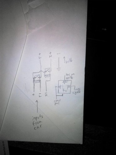
I think this should do it for you. 2 relays per side and an new ground connection. Clip all 3 wires at the plug. Connect the positive wire to pins 86 (coil) and 30 (relay switch). Connect the switched negative signal to pin 85 (coil). Pin 87 (relay switch) will now put out switched positive. Repeat 3 more times.

Connect the appropriate switched positive outputs to the former switched negative wires on the bulb connector. Connect the new body-negative to the old positive wire on the connector.

You'll probably need load resistors bridging positive to high/blinker/major negative to cancel the bulb out warning.

2015-02-08 19.08.45.jpg
 
Also when buying switchbacks make sure to get type 2... type 1 the white leds are always on and then the amber leds come on along with the white which makes the amber hard to see... I put some type 1 in my wifes car and am going to swap them put... type 2 the whit leds turn off while the amber flashes making the amber turn much more visable...
 
View attachment 828471525

I think this should do it for you. 2 relays per side and an new ground connection. Clip all 3 wires at the plug. Connect the positive wire to pins 86 (coil) and 30 (relay switch). Connect the switched negative signal to pin 85 (coil). Pin 87 (relay switch) will now put out switched positive. Repeat 3 more times.

Connect the appropriate switched positive outputs to the former switched negative wires on the bulb connector. Connect the new body-negative to the old positive wire on the connector.

You'll probably need load resistors bridging positive to high/blinker/major negative to cancel the bulb out warning.

Thanks for this LSFrank. However, this looks like Chinese translated into Portuguese translated into a dead language to me. I'm like a girl when it comes to electrical stuff. I know how to plug stuff in and turn it on and off. That's about it. LOL
:confused::confused::confused::confused::confused::confused::confused::confused:
 
resistors are the trick to make this work properly, no ones been able to get it quite right yet.

1st gen is different from 2nd gen too FYI
 
resistors are the trick to make this work properly, no ones been able to get it quite right yet.

1st gen is different from 2nd gen too FYI

Takes more than resistors for these. It'll take at least two resistors and two relays (or some transistors) per side to make those LEDs work on the LS.
 
Thanks for this LSFrank. However, this looks like Chinese translated into Portuguese translated into a dead language to me. I'm like a girl when it comes to electrical stuff. I know how to plug stuff in and turn it on and off. That's about it. LOL
:confused::confused::confused::confused::confused::confused::confused::confused:

I'll try to make a better drawing later on a real piece of paper, instead of on an envelope. Regardless, look up "relay pinout" and match wires to numbers

1st gen is different from 2nd gen too FYI

I'm not sure what's different, but for reference, I followed the labeling on my blinker socket and made some guesses about wire color vs. polarity. "Major" and "Minor" have black wires with stripes. "GND" has a red (ornage?) wire.

Takes more than resistors for these. It'll take at least two resistors and two relays (or some transistors) per side to make those LEDs work on the LS.

I would think the forward voltage of a transistor would hurt the already-poor performance of drop-in LED retrofits. LED clusters tend to put out light in the wrong spot for the reflectors, so reducing the voltage and making them dimmer would only hurt performance more.

But then again, I've spent the last couple weeks over at HIDPlanet and I'm probably too biased for having no real-world experience with the LS yet. They just tend to look like spots of light without using the reflectors properly. If Izzy uses the clear turn signal lenses, being that they're diffusers, it probably won't matter.
 
...I would think the forward voltage of a transistor would hurt the already-poor performance of drop-in LED retrofits. LED clusters tend to put out light in the wrong spot for the reflectors, so reducing the voltage and making them dimmer would only hurt performance more....

Drop across the transistors won't be a problem at all. This is true for either FETs or bipolars. The current needed by the LED is relatively small, and it would be easy to get FETs with very little on-resistance. In the case of bipolars, as long as they can handle the current, you just have to drive them to saturation. (Please note that the 0.7 base voltage for bipolars and the gate voltage for FETs has nothing to do with the on-state voltage drop.)
The difficulty with using a transistor circuit is that the bulb-minder circuit intentionally leaks some current in the off state. This means the circuit to drive the base (bipolar) or gate (FET) can't just be a simple resistor or two. All in all, while much bulkier, using relays will be a lot simpler.
 
It's been a while since I used them. Last time I opened that tray was when I thought I could make a MIRT (Mobile Infrared Transmitter) with a handful of IR LEDs and an Arduino.

I quickly realized that A.) they weren't powerful enough and B.) I don't even drive through the city.
 
View attachment 828471525
asshole..... lmfaoooo
I think this should do it for you. 2 relays per side and an new ground connection. Clip all 3 wires at the plug. Connect the positive wire to pins 86 (coil) and 30 (relay switch). Connect the switched negative signal to pin 85 (coil). Pin 87 (relay switch) will now put out switched positive. Repeat 3 more times.

Connect the appropriate switched positive outputs to the former switched negative wires on the bulb connector. Connect the new body-negative to the old positive wire on the connector.

You'll probably need load resistors bridging positive to high/blinker/major negative to cancel the bulb out warning.

View attachment 828471525
 
still waiting on upgraded diagram now that original posting has no diagrams anymore (that at least i kno i cant see)
 

Members online

Back
Top