Secondary Air Injection Systems
Overview of Electric Secondary Air Injection System
The Electric Secondary Air Injection (AIR) System (Figure 1) has an electric air pump which controls emissions during the first 20 to 120 seconds of engine operation. The AIR system forces air downstream into the exhaust manifolds to oxidize the hydrocarbons and carbon monoxide created by running rich at start-up.
The AIR system consists of an Electric Air Pump (EAP), a combination Check and Air Diverter (AIRD) valve(s), an Air Injection Bypass solenoid, a Solid State Relay, Powertrain Control Module (PCM) and connecting wires and vacuum hoses.
When the engine is started, the PCM signals the Solid State Relay and the Air Injection Bypass solenoid, after a few seconds delay, to begin system operation. The Solid State Relay provides the start-up signal and switches the high current required to operate the EAP. The EAP provides air until the catalyst is lit-off and can oxidize and reduce emissions. The Air Injection Bypass solenoid applies a vacuum to the AIRD valve(s) causing it to open allowing air to flow into the exhaust manifold through the inlet. The inlet contains a splash cap that prevents dirt and water from entering the EAP. Once the catalyst is lit-off, the PCM signals the Solid State Relay to stop pump operation and the Air Injection Bypass solenoid to stop the vacuum supply to the AIRD valve(s).
Figure 1: Dual AIRD Valve Secondary Air Injection (AIR) System
Figure 2: Single AIRD Valve Secondary Air Injection System
Hardware
Electric Air Pump
The Electric Air Pump (EAP) (Figure 3) provides pressurized air to the Secondary Air Injection system. The EAP functions independently of engine speed and is controlled by the PCM. The EAP is only used for short periods of time. Delivery of air is dependent on the amount of system backpressure and system voltage. The inlet system of the pump incorporates a non-serviceable filter and Splash Cap which helps to guard against dirt and water.
Figure 3: Electric Air Pump
Air Bypass Solenoid
The Secondary Air Bypass Solenoid (AIRB) (Figure 4) is used by the PCM to control vacuum to the Secondary Air Control Valve (ACV). The AIRB solenoid is a normally closed solenoid. The AIRB solenoid also has a filtered vent feature to permit vacuum release.
Figure 4: Secondary Air Bypass Solenoid
Air Diverter Valve
The Air Diverter (AIRD) valve (Figure 5) is used with the Electric Air Pump (EAP) to provide on/off control of air to the exhaust manifold and catalytic converter. When the EAP is on and vacuum is supplied to the AIRD valve, air passes the integral check valve disk. When the EAP is off, and vacuum is removed from the AIRD valve, the integral check valve disk is held on the seat and stops air from being drawn into the exhaust system preventing the back flow of the exhaust into the Secondary Air System.
Figure 5: Air Diverter (AIRD) Valve
Solid State Relay
The Solid State Relay (Figure 6) switches the high current required for operation of the Electric Air Pump (EAP). Control input to the Solid State Relay comes from the Powertrain Control Module (PCM).
Figure 6: Solid State Relay
Overview of Mechanical Secondary Air Injection Systems
The Mechanical Secondary Air Injection system (Figure 7) has a belt driven air pump which is utilized in electronic control systems to divert secondary air either upstream to the exhaust manifold check valve or to the downstream check valve and catalyst. The system will also dump secondary air to the atmosphere during some operating modes.
The typical Secondary Air Injection Diverter (AIRD) valve is used to direct the air either upstream or downstream.
The typical Secondary Air Injection Bypass (AIRB) valve is used to dump air to the atmosphere (Figure 7).
Examples of other Secondary Air Injection systems are shown in Figures 1 through 16.
Figure 7: Typical Secondary Air Injection (AIR) System
Dual (AIRD) Valve Secondary Air System on 7.5L.
The Dual (AIRD) Valve Secondary Air System is used exclusively on vehicles that come equipped with the 7.5L engine. However, not all 7.5L vehicles have this type of Secondary Air System, (Figure 8). The system has a single AIRB valve to control dual AIRD valves, one for each exhaust bank.
Figure 8: 7.5L
Single AIRB Solenoid and Valve on 5.0L Calif. Truck
This Secondary Air System represents a typical single AIRB Solenoid and single AIRB valve. The AIR is either bypassed or directed upstream. This system is basically used on the 5.0L California only trucks. On 7.5L trucks, which use this system, the air pump will direct air downstream to the catalyst.
Figure 9: 5.0L California
Typical Secondary Air System on 4.9L and 5.0L Truck
This Secondary Air system is utilized primarily on the 4.9L and 5.0L E/F Series truck. Although this system shown has a separate Air Diverter and Air Bypass valves, some E/F series trucks can have the commonly used Combination Air Diverter Air Diverter/Air Bypass valve.
Figure 10: 4.9L and 5.0L
Air Pump
The Air Pump is a belt-driven, positive displacement, vane-type pump that provides air for the Secondary Air Injection system. It is available in 19 and 22 cubic inch sizes, either of which may be driven with different pulley ratios for different applications. Pumps receive air from a remote silencer filter, the clean air side of the engine air cleaner attached to the pump's air inlet nipple, or an impeller type centrifugal filter fan.
Figure 11: 19 and 22 Cubic Inch AIR Pump
Air Silencer
The Air silencer is a combination silencer and filter for air supply pumps. The air silencer is mounted in a convenient position in the engine compartment and is connected to the AIR pump inlet by means of a flexible hose.
Figure 12: Typical AIR Silencer—9G427
Air Pump Resonator
The Air Pump Resonator (Figure 13) reduces air dump noise during cold start and some cruise modes.
Figure 13: Air Pump Resonator
Check Valve
The Air Check Valve (Figure 14) is a one-way valve that allows secondary air to pass into the exhaust system while preventing exhaust gases from passing in the opposite direction.
Figure 14: Air Check Valve
Combination AIRB/AIRD Valve
The Combination AIRB/AIRD Valve combines the Secondary Air Injection Bypass (AIRB) and Air Diverter (AIRD) functions. The valve is located in the air supply line between the AIR pump and the upstream/downstream air supply check valves.
The AIRB portion controls the flow of secondary air to the exhaust system (air control portion of the valve) or allows secondary air to be bypassed to atmosphere. When air is not being bypassed, the air control portion of the valve switches the air injection point to either upstream or downstream location. This portion of the valve is called secondary air injection diverter (AIRD).
Figure 15: Combination AIRB/AIRD Valve
Normally Closed AIRB Valves
The AIRB valves are normally closed valves which supply air to the exhaust system with medium and high applied vacuum signals during normal (engine at normal operating temperature) modes. With low or no vacuum applied, the pumped air is dumped through the silencer ports of the valve or through the dump port.
Figure 16: Normally Closed Secondary Air Injection Bypass (AIRB) Valves
Normally Open AIRD Valves
The normally open AIRD valve without a vacuum vent directs air pump output upstream to the exhaust manifold or downstream to the catalyst system depending upon the engine control strategy. The AIRD valve may also be used as a valve (Figure 18), directing air to the catalyst/exhaust system or to a remote air dump location depending on engine control strategy. A pressure relief valve also provides AIR pump protection in the event of excessive exhaust back pressure or system blockage.
Figure 17: AIRD Valves Without Pressure Relief
Figure 18: AIRD Valve
Normally Closed AIRB Solenoid
The Normally Closed Secondary Air Injection (AIR) Solenoid Assembly (Figure 19) consists of two vacuum ports with an atmospheric vent. The solenoid assembly can be with or without control bleed. The outlet port of the solenoid is opened to atmospheric vent and closed to the inlet port when de-energized. When energized, the outlet port is opened to the inlet port and closed to atmospheric vent. The control bleed is provided to prevent contamination entering the solenoid assembly from the intake manifold.
Figure 19: Solenoid Vacuum Valve Assembly
Dual AIRB and AIRD Solenoids
The Dual Secondary AIR Control Solenoid (Figure 20) assembly contains two normally closed vacuum solenoids. One solenoid controls the AIR Bypass (AIRB) valve and the other solenoid controls the AIR Diverter (AIRD) valve. Both solenoids vent when de-energized and are supplied by the intake manifold vacuum and controlled by the Powertrain Control Module (PCM).
Figure 20: Dual Secondary AIR Control Solenoids
Note: The solenoids can be expected to have a very small leakage rate when energized or de-energized. This leakage is not measurable in the field and is not detrimental to solenoid function.
Vacuum Check Valves
A Vacuum Check Valve (Figure 21) blocks air flow in one direction. It allows free air flow in the other direction. The check side of this valve will hold the highest vacuum seen on the vacuum side.
Figure 21: Vacuum Check Valve
Vacuum Reservoirs
The Vacuum Reservoir stores vacuum and provides "muscle" vacuum. It prevents rapid fluctuations or sudden drops in a vacuum signal such as those seen during an acceleration period.
Figure 22: Vacuum Reservoirs

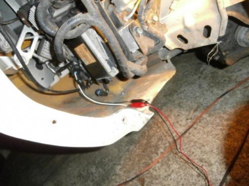
Possible Solutions If you have access to a scan tool, with KOEO (Key on engine off) command the AIR pump solenoid on and off. If the solenoid doesn't operate then unplug the solenoid and using a voltmeter, check for voltage being supplied to the solenoid when commanded on and also for good ground. If there is voltage being supplied and a good ground check for a good connection at the solenoid wiring harness connector. If the connection is good then replace the solenoid. If there is no voltage supplied to the connector when commanding the solenoid on, then find the AIR pump relay and verify that there is fused battery voltage present at the switched side of the circuit that is feeding voltage to the AIR pump.If not, check for blown fuse or open in the wiring. Repair and retest. If battery voltage is present at the voltage feed side of the relay, then a fast way to check for proper solenoid and AIR pump operation is to use a fused jumper and manually activate it. Do this by jumpering battery voltage to switched AIR pump voltage feed. Usually this is terminals 30 and 87 of the relay schematic (not always). If the solenoid (and possibly the AIR pump) operates, then you know your wiring and solenoid are okay. If it doesn't activate, open the wiring harness and find the open or short in the voltage feed to the AIR pump solenoid and fix it. If jumpering the solenoid to battery voltage activates the solenoid, then it's time to check for voltage present with KOEO on the PCM controlled side of the relay. If there is none, again repair open or short in the circuit and retest. To check the PCM wiring of the AIR pump solenoid, grounding the control circuit that is normally operated by the PCM will tell you if the wiring is intact. Grounding the circuit at the PCM connector with KOEO should activate the AIR pump relay, which in turn should activate the AIR pump & solenoid. If this doesn't work, then there is an open or short in the PCM control circuit. If grounding the control circuit operates the AIR pump and solenoid, verify the PCM has good ground paths and no damage to the connector or water intrusion. If that checks out, suspect an open driver in the PCM.
FMC DEALER


