500+ HP rear Axles?

Joe,
Great write up. Your 8.8 diff research shows well thought out procedure and diligence. Have you gotten a price quote on resplining the vette halfshafts to the expedition cv spider? On my griffith project the distance between cv joints will be around 8", does it look like there's enough od on the c5 shaft at that reduction for resplining? The c5 hub design that will allow attachment to custom uprights that fit inside 13" diameter formula atlantic wheels is yet another positive direction on your part.
Thanks again for sharing your wisdom that's help tackle a huge hump in this project,
Kevin
 
Joe,
It looks like the ford 4x4 front hub that attaches to that f150 halfshaft will work for making a custom upright to avoid re-splining. The halfshaft will still have to be sectioned and welded but that appears to be more low buck than re-splining. Did you find a better way of removing the cv spider off the halfshaft?
Thanks, Kevin

I am not a fan of sectioned and welded axles. Perhaps others have an opinion on this.

Regarding getting axles apart, I've found that the older they are and the higher the mileage is, the harder they can be to get apart. All new ones I purchased came apart with little effort using a slid tube, no press was needed.
About 1/2 a year ago I called a CV shaft refurbish company and asked why I couldn't get some of my axles apart, and they stated they have about a 30% attrition rate with used axles where the axle retaining clip is corroded or wont compress and release.

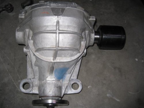
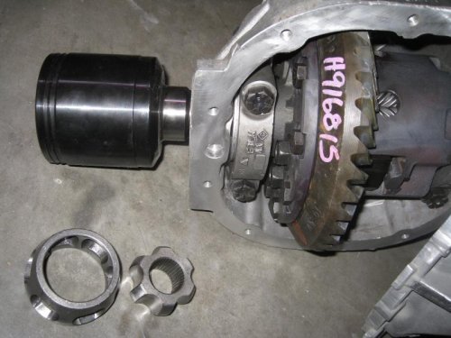
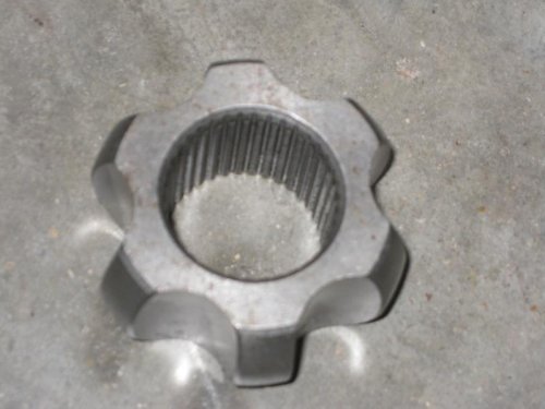
Attached are a few images of my differential, with the F150 CV hub slid into the housing, but not seated. The Splined race has 37 splines on roughly a 30mm ID.
IMG_4339.jpgIMG_4340.jpgIMG_4342.jpg

IMG_4339.jpg


IMG_4340.jpg


IMG_4342.jpg
 
Last edited:
Joe,
When you say "new ones you purchased" where did you get those? Since the '09-'10 late model front 4x4 hubs are a six bolt pattern and finding a small rotor to fit that and inside a 13" diameter wheel might be difficult five bolt hubs were researched. The '02 ranger 4x4 hub has a 5x4.5" lug pattern and the half shaft length looks short enough to fit without alteration. It appears ordering parts is needed unless there's an online source showing spline counts and measurements.
Thanks, Kevin

I was speaking generically. The new C5 Corvette, axles, New F150, Axles, and a new Jaguar S-type Axle. The point was that new axles are easy to take apart, the older they are, the more difficult they can be to take apart. The majority of the axle assemblies I purchase are from E-bay or Rock Auto.

I am only using the F150 CV hub with inner race (As shown in the images above.) The "short" axle and outer CV Joint on the F150 fit into the Fords' 4WD hub and is useless to me. As stated earlier, I mate to a Corvette C5/C6 outer CV hub. In my case, the Corvette splined axle is long enough and large enough of a diameter to have shortened and resplined.

I don't have a clue what spindle/hub you are trying to mate with on your Griffin project. C5/C6 spindles will only work with 18" and larger wheels.

The primary interest on this forum is for axles that mate a Mark 8 differential to LS hubs!
 
Last edited:
Interesting. Too bad a solution couldn't have been reached using the stock knuckle or even a modified OEM knuckle.

If you weren't trying to change the stance of the car to squeeze 19x10's under the back, do you think the C5 hubs would have been able to bolt into the OEM arms? As much as I like where you are going and want to do the same, I don't really want to fabricate arms that much.

The stock hub carrier is a very compact chunk of aluminum. As you've probably observed, it has the hub bearing pressed into the carrier housing and retained with a "C" ring. The same design approach was used on the Mustang Cobra IRS, but the Cobra hub carrier used a narrower bearing. (Same OD and ID dimensions) The Hub is lightly pressed into the bearing. The splines on the axle stub then slip into the hub's splines and get bolted together. Neat compact design that was originally intended for use with 16" wheels. This compactness of design works against you to try to do any modifications at all because there is little to no flat surfaces or extra material around the hub bearing area. I ran into difficulties trying to put on a 14.4" rotor on the Jaguar STR version of the hub carrier, where I couldn't design caliper adapter flanges that would mount Brembo calipers. (Rear + parking Caliper.) I 3-D modeled a lot of the hub carrier, and no matter how I tried to fit the calipers, I couldn't get it to work for what I wanted/needed.

I believe that the design can handle more power, but it was becoming too expensive to try to get it to work for what I wanted to do. It became less expensive overall to start fresh. When you can purchase complete C5 rear spindle assemblies for less than $200 each that includes the parking brake assembly, rod ends and hub. The C5 toe rods are half the price of skock LS toe rods, With these savings I could afford to make my own control arms. Look at the cost of replacing those crappy bushings in the lower control arm! I built up a complete new control arm for about the price of the bushings alone!

I also don't like having that third outboard bushing on the control arm. I'd much rather use spherical rod-ends/ball joints to control/hold the spindle. Much stiffer design.

I am putting on 19 X 12 rims, not 19 X 10.

Joe
 
Well if I had access to a machine shop still i'd be right there with you. Unfortunately I don't and I wouldn't just trust any place to make suspension components. Still curious to see how it all turns out for you.
 
Joe,
Internet research on 8.8 diffs started with the t2r given your direction and this thread turned up;
http://forums.corral.net/forums/road-racing-auto-x/1079376-t2r-problems.html
had you seen this, any comments?
Thanks, Kevin

I read this thread and a few others pertaining to the Torsen T2R. I purchased the T2R primarily for its 3.5 bias. I read about the problems. I purchased mine directly from Torsen in early 2013, and they claimed that the generation I purchased has not seen any issues so far. This brand/model was recommended to me through my brother via several of his associates who use the Torsen in their track-day cars.
 
I know a lot of the SOLO2 guys who give up on stock class put in torsens. They tell me it's one of the best things you can do if your car has no form of limited slip.
 
Joe,
A 2010 f150 left front halfshaft was bought from partsgeek.com, the advertised sku is A1 Cordone 60211, A1 Cardone 60-2191 and it says refurbished. This halfshaft had the tripod setup versus the rzeppa? you had gotten. The tripod stub axle housing and bearing weights 7.5 lbs, do you know the weight of your rzeppa stub axle assembly? The f150 halfshaft was taken to three shops that were unable to remove the outer cv. If you will, please send me the exact model and where you ordered your halfshaft so hopefully that will come apart. If you know of a cv rebuilder that will sell the halfshaft unassembled that would be even better.
Thanks,
Kevin
 
Kumba,
The scca solo2 national champions in prepared and mod appear to lean toward the clutch type but those same clutch diffs can hurt more than help if not setup correctly. You can get a headache trying to understand breakaway torque and accel/deaccel ramp angles of clutch setups. And then pulling it in and out a dozen times to find the optimum can be a royal pain.
Here's an example of a well setup clutch diff in the hands of a national caliber driver;
https://www.youtube.com/watch?v=hIwxCF5n3d4
If you google search kiesel bugeye emod you'll see another clutch diff in action. If you google jeep emod you'll see the torsen that was in the runner up and five seconds behind the bugeye, ouch.
Kevin
 
I find the information in this thread to be of great interest. I have little doubt that I'll ultimately have to do something beyond stock components when I get the new engine in the car. My thought has been to change things out in such a way as to use a 9-inch carrier and to go to a pair of driveshaft-like half shafts. It's been my notion to use something such as the 'corvet'-type hub carriers and fabricate as necessary.

More anon.

KS
 
Very interesting and informative thread.

cammerfe, if you don't mind some fabrication look into installing a winters quick change rear end. The drift car comunity already uses them. There are no axle tubes. The covers have been setup for irs drive shafts (and seals?).

On a separate note, one of the members of the gt40 kit car community has designed outer stubbs that mate the corvette knuckles to porsche axles. Porsche 930 style axles and CVs can take enormous amounts of torque and can be found fairly cheaply.

Good luck with your projects.
 
In fact, I have a Winters, left over from a circle track project from several years ago. But I also have another use for it in a car for an all-out effort at land speed racing.

The ubiquitous 9" has enormous support in the aftermarket and it's easy to get a fabricated housing in virtually any width.

Thanks for your good wishes!

KS
 
cammerfe, if you don't mind some fabrication look into installing a winters quick change rear end. The drift car comunity already uses them. There are no axle tubes. The covers have been setup for irs drive shafts (and seals?).

As you may know, the LS mounts the differential off of 2 points on the rear cover, and one point on the front. In order to put in a Winters quick change, you would have to modify the sub-frame and probably cut into the trunk in order to fit the module.

Regarding axles, I looked into Porsche CV and C6 combination of axles, and that is still a possibility for my axles. When I cruntched the costs last year, the approach I am taking was the most cost effective for the power I will be running.

I haven't ordered axles yet because I have been waiting since August last year to have custom lower taper pins fabricated. They are finally being fabricated, so I will soon be able to mount my new lower A-arms and set up the suspension so I can get final axle lengths. Too long and slow a process. In the mean time I have been distracted because I purchased another car that needs an engine rebuild.
 
Finally after 9 months of waiting, my custom rod end pin arrived. I am now able to put on my custom control arms and spindle together. Next step is to build up custom coilovers and purchase custom splined corvette to F150 1/2-shaft axles.

Anyone measure, calculate or figure out the "motion ratio" of the LS rear suspension? Can anyone confirm the shock travel?
(I measured 3" of travel.) Has anyone measured the suspension travel? Travel up and down from a neutral stance? (I am working on measuring and figuring it out, but it would be nice if someone could confirm.

IMG_0174.jpg


IMG_0160.jpg
 
I installed a 2010 Camaro LS3 engine with a TR6060 6-speed into a 2000 S-type. Presently around 430 HP, with future plans for 550 to 600HP.
I posted on this forum because more of you modify your LS's than S-type owners and the cars are so similar suspension wise.

The suspension is being upgraded to use 345/30/19 tires in back and 305/30/19 tires on the front.

The car will be a street car, but I want to run it on track days and perhaps autocross it. (In comparison the car will be a bit lighter than 2010 to 2013 Camaros, with equivalent HP, and better handling. So if a Camaro can do well on the track, so will this car.

Putting the car together has been a long slow process, and I want to have an axle set-up that will handle 600 HP, with a lot more torque than a stock 4.2 engine. Since I am already putting a MK8 carrier into the car, I am trying to find the best axle set-up without having to spend $2K.

Any axle ideas?

sorry, dont mean to hi-jack your thread. i'm really interested in how you did the lsx swap. i actually bought my car with that intent as soon as something major craps out. i've seen them done but never anyone that's active on a forum that you can ask questions and get some finer details.
 
I'm personally don't like the practice of using a rod end bearing on the outboard side of a control arm. The threads are stress concentrators and due to bending moments rod end bearings usually fail right where threads start. The consequences could be catastrophic. I would prefer a monoball bearing that's enclosed by the control arm and mounted in double shear. I would also like to have a standoff/large washer to keep the control arm connected to the knuckle in case the monoball bearing breaks if mounted in single shear. You could also look into "adjustable upper and lower ball joints" by companies such as allstar, howe, afco etc. They are made for the circle track community and fit standard gm/chrysler rwd platform suspension arms. An adjustable ball joint is basically a monoball bearing installed in a balljoint type housing with a through pin that looks like your rod end pin so that it may be fitted to a standard control arm and a standard knuckle. I do know that allstar makes two different reamers so the knuckles could be modified to fit the balljoint taper (something like a 7.15 one deg and a 9.56 one degree but don't quote me on numbers). Some of these could be seen on summit racing or lane automotive web pages. I have no affiliation with above mentioned companies.

It's a bit late to ask about the LS motion ratio. If you are using custom control arms you would have to calculate or just measure your new motion ratios both for dampers and anti-sway bars. Unless corvette knuckles are identical to LS knuckles your suspension kinematics have changed as well. You ought to calculate what your suspension will do. Terminal bumpsteer is a joykill. There is software available, you could do it numerically or just build a physical copy (a model) and measure.

Check the following page (no affiliation) http://www.hemipanter.se/ It's an old school layout but it does have a trove of relevant info.

On another note, usually the weakest link in a chain fails. The point is that if you make the rear end bulletproof the next thing that fails may be a drive shaft, an output shaft, an input shaft, a gear, etc., so one ought to take a look where the drive train "fuse" ought to be. If you are lucky a clutch. As you know, it's sudden loads that damage stuff - curb hopping on track, aggressive launches on slicks, etc.

This shouldn't be taken as an attack on you or your project, but as ramblings brought by seeing a pic of your rod end pin.

Good luck.
 
I don't disagree with anything you wrote. But, I am using a 1" diameter threaded rod end. (total mass = 2+ pounds. Very robust for this application. It will take a long long time to fatigue across a thread. I'll have to go back and look at my cyclic stress calculations, but when I ran an FEA on the rod ends and arm, the deformation and flexure was very small.
The rod end will take an impact of over 76000+ pounds and my calculations show that an impact of this magnitude will destroy the rim before it gets close to bending along the threaded portion.

I chose to go with an outboard lower rod end for several reasons. 1. Adjustability, 2. Ease of fabrication. 3. This size rod end has been used successfully on Off-road lower suspensions that take one hell of a beating and don't fail.

My suspension is 3D modeled in Solidworks and I do have 2 alternate lower control arm designs. One that used a Mono-ball bearing, and the other a more standard press in ball joint. I figure that once I iron out the geometry and get everything adjusted, I can go back and fabricate a more weight optimized fixed-geometry lower A-arm. Presently I am adding at least couple pounds more than a stock lower control arm.

Regarding, motion ratio and suspension travel, I have what I believe will work figured out, but was hoping that someone else has some numbers I could compare to.
 
MIdsm: I did some follow-up calculations on the cyclic loads that this rod end will see and am satisfied that it is robust enough to have an infinite life. I ran some numbers for cyclic fatigue based on using a notch radius for the minor diameter of the 1" thread. Looked at greatest moment distance for a thread next to the jam nut. I ran numbers using 1000lb and 5000lb cyclic loads. (Total car weight is less than 4000lbs, so 1000 pound is a reasonable load number.) At +-1000lbs, Fatigue cycle, I generated a Fatigue-Failure S-N curve, the calculations indicate infinite life. At +-5000lbs, the results lie just inside the finite life part of the curve.

I still need to run some numbers based on applying "braking loads" on the rotor, and add in these torsion effects. I also need to determine what cyclic bending moments get generated during severe braking. These loads are not continuous like the suspension travelling up and down, but could be significantly larger forces.
 
Finally: One of my 8.8 31 spline 1/2 shaft custom axles is assembled. Took several months for the axles to be fabricated, rather than the 3-4 weeks quoted. Remember if you keep track of this thread, these axles are for my LS/S-type sub-frame with a Mark 8 Torsen LSD differential, and Corvette outer spindles.

Perhaps not too exciting, but they are significantly beefier than stock. Axles are 4340. Decided I didn't need to spend the extra on 300M.


Enjoy

IMG_0236.jpg
 
Last edited:
I am bumping this thread to ask a few questions! I am trying to replicate what you have done here. I am also trying to make custom beefy axles on a budget. Few seem to have tried this and there is little information online!

Do you have measurements or specs of the Explorer "37 spline" CV axles? I can't find the specs on these anywhere. I believe they must be a different pitch than the standard axle splines (which are 24 spline typically). If you have the major diameter I think I can figure it out. Maybe these CV axles use a metric pitch?

Were the front inboard CVs off the F150/Explorer different than the rear ones? I wasn't clear if you also looked at the rear axles. I was presuming I could try to use rear inboard Explorer CV's, but maybe these are different in some way?

So did you end up machining the differential housing to take the larger truck sized seal? Actually it sounds like you managed to find a special seal that would fit in the axle housing but had the right ID? That is brilliant! I have a lathe and was presuming I could just turn down the seal diameter but this is easy peasy!


Really appreciate all your work on this. We think alike! Hope you are still on the forum after 7 years :) Looks like you signed in earlier in the year at least!
 

Members online

No members online now.
Back
Top